Friday, November 9, 2007

Door Fitting

A summary of the process of fitting the old doors into new frames.

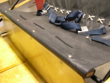
First insert the doors into the frame and estimate what a nice even gap all around would be.  Mine looked like a 1/4 inch gap would be about right, so I taped pieces of 1/4" shim material around the frame.

The shims hold the door in position temporarily while locating the hinge positions.  So the next step is to clamp the door into the frame...the shims holding an ideal gap all around.

I used 2 "C" clamps on the hinge side and a spring clamp at the latch side.  Then while the door was being held by the clamps, I drilled the holes for the hinges and marked the position of the latch.  After removeing the door/clamps/shims from the frame, I permanently through bolted the hinge halves to the wood frame and remounted the door to the hinges for a test fit.  Not quite perfect!  So I had to "fine tune" the fit.

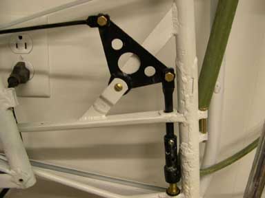
I found I could control the "twist" of the door (getting the top and the bottom of the door to meet the frame at the same time when closing it) by shimming a very slight angle into the door frame.  I added a .050 Aluminum shim under one side of the frame mount shown at the bottom of the photo.  And I could control the up-and-down position of the latch strike by shimming the hinges away from the frame or in this case (top of photo) by chiseling a little pocket and letting the hinge "into" the frame.  Very small changes in hinge position and frame twist translate into much larger changes at the latch end.


And finally, I had to fabricate new latch plates.


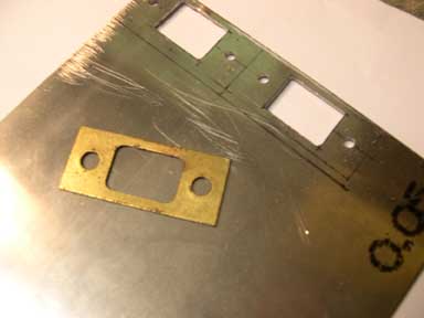
Shown on the left of this photo is the old, original latch plate.  It is made of brass plated steel.  On the right is the layout of two new plates on .050 4130 steel.  The holes have been drilled and the center openings drilled and filed out, the plates are ready to be hack sawed free, cleaned up and epoxy painted.

Return to Index


Wednesday, November 7, 2007

Elevator trim

The elevator trim consists of a crank/pulley in the cockpit.

Connected by a 1/16" cable to the trim mechanism in the horizontal stab.

And by a rocker arm to the elevator trim tab.

The trim mechanism needed cleaning and lube.   The rocker arm bushing are made of 1/4 OD brass tube available from hobby stores and fine hardware stores.  My pulleys were both in very rough shape.  I had to re-form the groove on the forward pulley to make it a sharp "V" so it will grip the cable.

I chucked the pulley in the drill press and then used a "knife edge" needle file to form the groove.  I also found it necessary to repair the outer edge of the pulley which was chipped and broken.


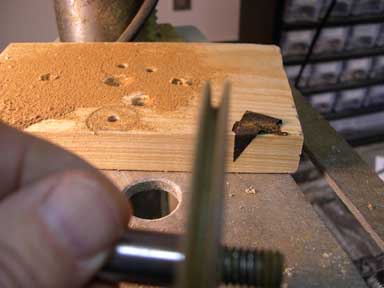
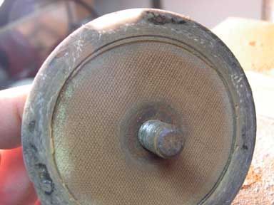
I used epoxy resin and a few strands of glass liberated from the fringe of a glass deck cloth.  The ID is formed by an old spray paint can lid, and the groove is formed by masking tape.  The pulley was then sanded (on the drill press) and painted.  The light colored portion of the rim in the picture above is the repair.

Return to Index 


Stringers

There appear to be several types of T-Craft stringers.  Many folks purchase off-the-shelf "T" style stringers from Aircraft Spruce and they work fine except they are expensive and unnecessarily heavy.   I believe mine are the original style..simple spruce strips, 1 inch wide and tapered in thickness from 3/8 to 1/4.  You can easily make a whole airplanes worth in a few minutes with a table saw and some scrap spruce (old wing spars?)  Simply rip your spruce stock into 8-1" X 3/4" strips, then rip each strip again with the table saw blade set at about 10 degrees.  Each spruce strip yields two tapered stringers.   

They are secured to the fuselage frame with cotter pins.

At the door frame with steel angles (.050 thick 4130 steel... drill, bend, paint)  Note the door frames are also made of recycled spar material.


And the stringers are attached to the frame at the aft end with anti-chafe tape (cloth, adhesive tape).  Give the tape a couple coats of epoxy varnish.

Link to Wood Recycle

Return to Index

Tuesday, October 16, 2007

floorboards

my floorboards are 1/4" Baltic Birch plywood.   I used the aluminum floorboards as a pattern, cutting the plywood on the bandsaw.  A 1/4" X 3/4" spruce strip joins the two parts of the floorboards.  The only real trick to making them is getting the "bow" in the plywood pieces.  I used 8X8X16 concrete blocks as weights, 2X4 blocks, and soaked the plywood for several hours in water.


The brake heel plates are fabricated of .050 aluminum sheet and screwed in place with 3/8 SM screws.

The floorboards are installed one at a time with #8 screws and locknuts after four coats of varnish, 2 coats of traditional spar varnish and 2 of epoxy varnish, light sanded between coats

.

And then the kick panel (also 1/4 plywood) is added under/infront of the seat.

Return to Index

Monday, April 30, 2007

seat sling


The seat with cushions and seat belts.


Shown above is the "spider" that attaches the seat belts to the frame.

I sewed 6 Velcro loop strips to the seat sling...and six Velcro hoop strips to the cushions to hold the cushions in place. 

The seat sling itself is then laced onto the spider using a shoelace type pattern.

And then the seat sling is rolled onto the front "seat adjustment" batten and screwed to the steel framework above the kick panel. 

Return to Index

Wednesday, February 7, 2007

Glove box

Taylorcraft glove boxes seldom survive.  They are often removed in favor of "modern" radios and instruments.  And, the original glove boxes were made of cardboard    so if they got wet or received rough handling they were destroyed. 

Following suggestions from Tailorcraft owners, the glove box is long enough to hold a sectional chart flat, it is cut away in the top front ends to clear the boot cowl, and the front end is sized to hold two 6V. lantern batteries.  I made my glove boxes of thin fiberglass over an aluminum tray (Photo 1).  I first made a mold (real moldmakers would call this a "plug") from 3 pieces of 2X6 bandsawed to shape and glued together (Photo 2).  I used two layers of boat cloth and polyester resin. 

Next, I made door springs using the "How to Make Springs" website and a photo that Keith sent me.  The spring is 15 turns of .025 music wire. (Photo 3)  I first made some simple tooling...a 1/8 mandrel held in the chuck of a drill, and a forming tool made of a 1/2 x 1/8 x 12 bar with two holes in it.  The first hole is slightly over 1/8 so the mandrel can turn inside it, and the second hole, about 2" behind the first, is sized to tightly hold a 1/8 pin.  (Photo 4)  To make the springs, the forming tool and the music wire are held in the right hand while the left hand operates the drill.  About $2 worth of music wire will make a dozen springs in just a few minutes.  Photo 5 shows a spring installed in a hinge.

I also made glove box doors of .032 aluminum sheet.  Photo 6 shows the setup consisting of two oak blocks with the 5 x 7 aluminum sheet clamped between.  The block behind the aluminum has a radius filed onto three sides.  A rawhide mallet is used to hammer the aluminum down around the radius.  (Photo 7)

Return to Index


Tuesday, January 23, 2007

Brake Cables

Taylorcraft brakes are, of course, mechanical brakes actuated by cables.  The original size of the cables is a matter of some discussion.  Some say 1/16" cables were original, others say 3/32".  Adding to the confusion is the fact that most "T"s are now equipped with 1/8" cables which are standard for all other controls.  But the fact is the cables need to be quite flexible to go around those little steel pulleys...and 1/8" is just too large.  Then there's the reports of 1/16" cables breaking...breaking strength of 1/16" cable is 480 lbs., but one can easily imagine a panic stop with a 200 Lb. pilot stomping up to, well, 480lbs resulting in brake failure.  That leaves 3/32" cables, delightfully flexible in the 7X19 version with an astounding 1000 lb. breaking strength!

The cables are connected to the pedals with adjustable cable clamps.  Behind the pedals, the parking brake is connected with another cable clamp. (see Photo 1)  At the wheel, the cables are connected to the brake bellcrank with a nico press sleeve and thimble...and two steel links.  (see Photo 2)


Return to Index

Tuesday, January 2, 2007

Fairleads, Cable Guides

These fairleads are usually called cable guides, although they do the same job as the round kind.  The T-Craft has 4 cable guides, two 3 holers as shown in Photo 1, and two single holers.  They serve to route the elevator and rudder cables around the cockpit.  My project T had the right front cable guide missing...it is the one that gets the most wear and gives the most friction (due to the angle of the cables at this point).

But it's easy to make a duplicate part.  Cut two identical blocks of 1/4 thick phenolic using an old cable guide as a pattern.  Then drill the mounting holes 3/16".  Bolt the two blocks together and then drill the 3 guide holes down the center. (Photo 2) The drill bit will tend to follow the seam between the blocks giving two nice half-holes in each block.

Return to Index

Link to Fairleads, Phenolic

Monday, January 1, 2007

Fairleads, Phenolic

Nylon fairleads are easy and all "modern" looking.  But phenolic is original.   And lighter, and cheaper.  (Well, they're cheaper only if you ignore the labor required to fabricate them!)

I got my fairleads from Mark Julicher for $10/dozen.  They are simple sections of phenolic pipe and require some minor machine work to finish them.  All operations are easily done on a cheepo made-in-China drill press and some simple tooling.

I made fairlead mounting fixture for the drill press (Photo 2) by cutting the head off a AN3-15 bolt, drilling a 3/16 hole in a short piece of 5/8 dowl, a couple of washers and a AN365 nut.  Then I used a strip of plumbers sandpaper (Photo 3) wrapped around the fairlead to polish it down to around .790 outside diameter...a nice fit.

Then I used a 5/8 rotary rasp to open up the inside diameter (Photo 4).  (Test the fit by pulling a control cable through.)

To cut the retainer ring grooves, I made a "cup" fixture (Photo 5) from a piece of one inch steel tube with a washer soldered in one end.  The cup covers most of the fairlead but leaves about 1/8 of one end exposed.  The groove is cut with a hacksaw blade bearing against the phenolic and located by the cup fixture. (Photo 6).  Turn the fairlead around to cut the groove in the other end.

The resulting fairleads are identical to the original fairleads except for the fresh pink color. (Photo 7)

Return to Index

Link to Fairleads, Nylon