Friday, November 9, 2007

Door Fitting

A summary of the process of fitting the old doors into new frames.

First insert the doors into the frame and estimate what a nice even gap all around would be.  Mine looked like a 1/4 inch gap would be about right, so I taped pieces of 1/4" shim material around the frame.

The shims hold the door in position temporarily while locating the hinge positions.  So the next step is to clamp the door into the frame...the shims holding an ideal gap all around.

I used 2 "C" clamps on the hinge side and a spring clamp at the latch side.  Then while the door was being held by the clamps, I drilled the holes for the hinges and marked the position of the latch.  After removeing the door/clamps/shims from the frame, I permanently through bolted the hinge halves to the wood frame and remounted the door to the hinges for a test fit.  Not quite perfect!  So I had to "fine tune" the fit.

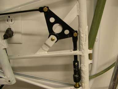
I found I could control the "twist" of the door (getting the top and the bottom of the door to meet the frame at the same time when closing it) by shimming a very slight angle into the door frame.  I added a .050 Aluminum shim under one side of the frame mount shown at the bottom of the photo.  And I could control the up-and-down position of the latch strike by shimming the hinges away from the frame or in this case (top of photo) by chiseling a little pocket and letting the hinge "into" the frame.  Very small changes in hinge position and frame twist translate into much larger changes at the latch end.


And finally, I had to fabricate new latch plates.
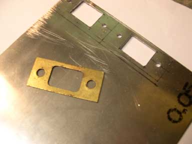
 

Shown on the left of this photo is the old, original latch plate.  It is made of brass plated steel.  On the right is the layout of two new plates on .050 4130 steel.  The holes have been drilled and the center openings drilled and filed out, the plates are ready to be hack sawed free, cleaned up and epoxy painted.

Return to Index


Wednesday, November 7, 2007

Elevator trim

The elevator trim consists of a crank/pulley in the cockpit.

Connected by a 1/16" cable to the trim mechanism in the horizontal stab.

And by a rocker arm to the elevator trim tab.

The trim mechanism needed cleaning and lube.   The rocker arm bushing are made of 1/4 OD brass tube available from hobby stores and fine hardware stores.  My pulleys were both in very rough shape.  I had to re-form the groove on the forward pulley to make it a sharp "V" so it will grip the cable.

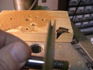
I chucked the pulley in the drill press and then used a "knife edge" needle file to form the groove.  I also found it necessary to repair the outer edge of the pulley which was chipped and broken.


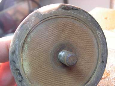
I used epoxy resin and a few strands of glass liberated from the fringe of a glass deck cloth.  The ID is formed by an old spray paint can lid, and the groove is formed by masking tape.  The pulley was then sanded (on the drill press) and painted.  The light colored portion of the rim in the picture above is the repair.

Return to Index 


Stringers

There appear to be several types of T-Craft stringers.  Many folks purchase off-the-shelf "T" style stringers from Aircraft Spruce and they work fine except they are expensive and unnecessarily heavy.   I believe mine are the original style..simple spruce strips, 1 inch wide and tapered in thickness from 3/8 to 1/4.  You can easily make a whole airplanes worth in a few minutes with a table saw and some scrap spruce (old wing spars?)  Simply rip your spruce stock into 8-1" X 3/4" strips, then rip each strip again with the table saw blade set at about 10 degrees.  Each spruce strip yields two tapered stringers.   

They are secured to the fuselage frame with cotter pins.

At the door frame with steel angles (.050 thick 4130 steel... drill, bend, paint)  Note the door frames are also made of recycled spar material.


And the stringers are attached to the frame at the aft end with anti-chafe tape (cloth, adhesive tape).  Give the tape a couple coats of epoxy varnish.

Link to Wood Recycle

Return to Index

Tuesday, October 16, 2007

floorboards

my floorboards are 1/4" Baltic Birch plywood.   I used the aluminum floorboards as a pattern, cutting the plywood on the bandsaw.  A 1/4" X 3/4" spruce strip joins the two parts of the floorboards.  The only real trick to making them is getting the "bow" in the plywood pieces.  I used 8X8X16 concrete blocks as weights, 2X4 blocks, and soaked the plywood for several hours in water.


The brake heel plates are fabricated of .050 aluminum sheet and screwed in place with 3/8 SM screws.

The floorboards are installed one at a time with #8 screws and locknuts after four coats of varnish, 2 coats of traditional spar varnish and 2 of epoxy varnish, light sanded between coats

.

And then the kick panel (also 1/4 plywood) is added under/infront of the seat.

Return to Index

Monday, April 30, 2007

seat sling


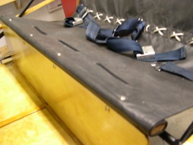
The seat with cushions and seat belts.


Shown above is the "spider" that attaches the seat belts to the frame.

I sewed 6 Velcro loop strips to the seat sling...and six Velcro hoop strips to the cushions to hold the cushions in place. 

The seat sling itself is then laced onto the spider using a shoelace type pattern.

And then the seat sling is rolled onto the front "seat adjustment" batten and screwed to the steel framework above the kick panel. 

Return to Index

Wednesday, February 7, 2007

Glove box

Taylorcraft glove boxes seldom survive.  They are often removed in favor of "modern" radios and instruments.  And, the original glove boxes were made of cardboard    so if they got wet or received rough handling they were destroyed. 

Following suggestions from Tailorcraft owners, the glove box is long enough to hold a sectional chart flat, it is cut away in the top front ends to clear the boot cowl, and the front end is sized to hold two 6V. lantern batteries.  I made my glove boxes of thin fiberglass over an aluminum tray (Photo 1).  I first made a mold (real moldmakers would call this a "plug") from 3 pieces of 2X6 bandsawed to shape and glued together (Photo 2).  I used two layers of boat cloth and polyester resin. 

Next, I made door springs using the "How to Make Springs" website and a photo that Keith sent me.  The spring is 15 turns of .025 music wire. (Photo 3)  I first made some simple tooling...a 1/8 mandrel held in the chuck of a drill, and a forming tool made of a 1/2 x 1/8 x 12 bar with two holes in it.  The first hole is slightly over 1/8 so the mandrel can turn inside it, and the second hole, about 2" behind the first, is sized to tightly hold a 1/8 pin.  (Photo 4)  To make the springs, the forming tool and the music wire are held in the right hand while the left hand operates the drill.  About $2 worth of music wire will make a dozen springs in just a few minutes.  Photo 5 shows a spring installed in a hinge.

I also made glove box doors of .032 aluminum sheet.  Photo 6 shows the setup consisting of two oak blocks with the 5 x 7 aluminum sheet clamped between.  The block behind the aluminum has a radius filed onto three sides.  A rawhide mallet is used to hammer the aluminum down around the radius.  (Photo 7)

Return to Index


Tuesday, January 23, 2007

Brake Cables

Taylorcraft brakes are, of course, mechanical brakes actuated by cables.  The original size of the cables is a matter of some discussion.  Some say 1/16" cables were original, others say 3/32".  Adding to the confusion is the fact that most "T"s are now equipped with 1/8" cables which are standard for all other controls.  But the fact is the cables need to be quite flexible to go around those little steel pulleys...and 1/8" is just too large.  Then there's the reports of 1/16" cables breaking...breaking strength of 1/16" cable is 480 lbs., but one can easily imagine a panic stop with a 200 Lb. pilot stomping up to, well, 480lbs resulting in brake failure.  That leaves 3/32" cables, delightfully flexible in the 7X19 version with an astounding 1000 lb. breaking strength!

The cables are connected to the pedals with adjustable cable clamps.  Behind the pedals, the parking brake is connected with another cable clamp. (see Photo 1)  At the wheel, the cables are connected to the brake bellcrank with a nico press sleeve and thimble...and two steel links.  (see Photo 2)


Return to Index

Tuesday, January 2, 2007

Fairleads, Cable Guides

These fairleads are usually called cable guides, although they do the same job as the round kind.  The T-Craft has 4 cable guides, two 3 holers as shown in Photo 1, and two single holers.  They serve to route the elevator and rudder cables around the cockpit.  My project T had the right front cable guide missing...it is the one that gets the most wear and gives the most friction (due to the angle of the cables at this point).

But it's easy to make a duplicate part.  Cut two identical blocks of 1/4 thick phenolic using an old cable guide as a pattern.  Then drill the mounting holes 3/16".  Bolt the two blocks together and then drill the 3 guide holes down the center. (Photo 2) The drill bit will tend to follow the seam between the blocks giving two nice half-holes in each block.

Return to Index

Link to Fairleads, Phenolic

Monday, January 1, 2007

Fairleads, Phenolic

Nylon fairleads are easy and all "modern" looking.  But phenolic is original.   And lighter, and cheaper.  (Well, they're cheaper only if you ignore the labor required to fabricate them!)

I got my fairleads from Mark Julicher for $10/dozen.  They are simple sections of phenolic pipe and require some minor machine work to finish them.  All operations are easily done on a cheepo made-in-China drill press and some simple tooling.

I made fairlead mounting fixture for the drill press (Photo 2) by cutting the head off a AN3-15 bolt, drilling a 3/16 hole in a short piece of 5/8 dowl, a couple of washers and a AN365 nut.  Then I used a strip of plumbers sandpaper (Photo 3) wrapped around the fairlead to polish it down to around .790 outside diameter...a nice fit.

Then I used a 5/8 rotary rasp to open up the inside diameter (Photo 4).  (Test the fit by pulling a control cable through.)

To cut the retainer ring grooves, I made a "cup" fixture (Photo 5) from a piece of one inch steel tube with a washer soldered in one end.  The cup covers most of the fairlead but leaves about 1/8 of one end exposed.  The groove is cut with a hacksaw blade bearing against the phenolic and located by the cup fixture. (Photo 6).  Turn the fairlead around to cut the groove in the other end.

The resulting fairleads are identical to the original fairleads except for the fresh pink color. (Photo 7)

Return to Index

Link to Fairleads, Nylon

Thursday, November 30, 2006

Control Cables

Inspect those cables.  The traditional method is to rub a rag the length of the cable...if the rag snags on a loose wire, replace the cable.  But really, ALL the cables on the entire airplane can be replaced for less than $100 and a bit of your own labor.  So why not treat the old girl to a new set of control cables?!

The tools required are modest (Photo 2).  A cable cutter, some thimbles, nicopress sleeves, and a swedge-it tool.  The swedge-it tool comes with a go/no-go gage or you can use a calipers to check the finished swedge.  Order enough cable, plus a little extra.  The Taylorcraft uses all 1/8" 7X19 galvanized cable...about 150 feet total.  You can buy genuine aircraft cable for about the same price as the hardware store stuff, so don't cheap out on the cable quality!

First cut off the old fittings.  (Photo 3) shows a bushing being cut off with a hacksaw.  Then tape the old cable side by side to the new cable.  Keeping the old and new cables taped together (Photo 4) until the terminations are complete will ensure that the new cable will come out exactly the same length as the old cable.

Wrapping the cut point with a couple turns of masking tape will keep the cable strands from spraying out when cut with the cable cutter (Photo 5)

Run the cable through the nicopress sleeve, around the thimble, through the turnbuckle end (if used!), and then back through the nicopress sleeve.  Allow 1/8 to 1/4 inch of the cut end to protrude through the sleeve.  (photo 6)  The sleeve expands lengthwise as it is swedged, so it will tighten the cable around the thimble and reduce the length of cable end protruding out of the sleeve. 

Then insert the thimble, end, sleeve, cable assembly into the swedge-it tool (Photo 7) and complete the swedge following the directions that came with the tool or from AC43.13.

Finally, check the completed swedge with the go/no-go gage (Photo 8)

Return to Index


Wednesday, November 15, 2006

Bungee Covers

Gary Austin let me use his original bungee covers.  (Photo 1) Bungee Covers, note cracks around mounting holes and riveted repairs

(Photo 2) Plywood mounting board holds the bungee covers for duplication.  I wanted to make the covers 3/8" wider to allow for some trimming to fit and close up the centerline gap between the L and R covers.  Also, I added a 1/4 " shim under the center of the originals to give a bit of preload to the spring effect.

(Photo 3) Bungee covers are attached to the mounting board with 1/2 inch aircraft nails around outside edges and given first coat of wax.

(Photo 4) Then the waxed bungee covers are given two layers of fiberglass and the base box is bedded into the still-wet resin.  In this photo you're looking at what will be the bottom of the finished mold.

(Photo 5)  The first part being removed from the mold.  It still needs to be cleaned, trimmed, painted, and cut into two individual covers.

(Photo 6) The finished composite bungee covers.

Return to Index


Thursday, November 9, 2006

Bungees

The bungees are removed by cutting them.  Be careful, the final snap can be a shock.

Get the proper tool to install new bungees.  David Rude makes an excellent tool (shown in Photo 1).   Read and carefully follow the directions that come with the tool.  Bungees can easily develop people maiming force.

Photo 2 shows the tool being used to install a bungee. 

Return to Index

Turnbuckles

Turnbuckles may simply be replaced with new or the old ones may be inspected, cleaned, refinished and returned to service.   At $25 each it's an easy decision.  ( There are 10 turnbuckles in a Taylorcraft!)

When you disassemble the turnbuckles the first thing you'll notice is that one end has left hand threads.  That end is marked with a ring around the barrel.  The turnbuckles may be difficult to turn, soak them overnight in a penetrating oil.  Once you have them disassembled, clean all parts with a toothbrush and mineral spirits.

The barrels are made of bronze and are likely to have turned a dull gray color.  You can return them to a beautiful golden hue with a scotchbrite pad and some metal polish.  (Photo 2).  Clean the internal threads by screwing an old turnbuckle end in and out a few times with a drop of marvel mystery oil.

Turnbuckle ends are galvanized steel.  If the plateing is intact you may simply clean and reuse them.  But you're likely to find that most have a light surface rust starting.  (deeply rusted, pitted ends should be rejected)  Give them a light bead blasting to remove the rust and a double coat of epoxy primer.  (don't paint the threads!)

Small parts like turnbuckle ends may be blasted in a kitchen strainer like shown in Photo 3 or they may be attached to a board for blasting and painting like Photo 4.  I prefer mounting them to a board since it protects the threads from blasting and painting.

AC43.13 shows how to assemble and safety wire your turnbuckles.

Return to Index

Thursday, October 19, 2006

Aileron Leading Edge

The aileron leading edge is much more difficult to install than the wing leading edge.  Reason?  The aileron leading edge must be bent around a smaller radius.  It take quite a bit of force across the 4 foot wide sheet of aluminum to get it to bent that tight.  One solution: get a couple of helpers and use 4 to 6 hands at once to bend it around.

But if you're like me (working by myself most of the time!) you'll need to use this little trick.  First, tack the leading edge to the spar along the bottom of the aileron.  Use those little 3/8" aircraft nails in the spar and a few #4 screws into the ribs.  Then bend the leading edge part way around and tie it in place with a 2' length of 1/4" nylon rope.  Move a little further down and do the same thing again.  (Photo 1)   Continue bending and tieing until the entire leading edge is partially bent.  (Photo 2)   Add a row of screws to hold it in place, then bend it a little more and tie it again...add more screws.  Bend, tie, screw...bend, tie, screw...until it's done! 

Go to Aileron Assembly page

Return to Index

Wednesday, October 18, 2006

Aileron Assembly

Procedure for assembly of the aileron:

1. Transfer the rib locations, reinforcement locations, and hardware locations from the old spar to the new spar.  Glue and nail the center reinforcements onto the new spar.  Varnish everything except the inboard and outboard reinforcement locations.

2. Slide the ribs onto the spar. I use the vertical wing assembly jig with the uprights moved closer together. (Photo 1)  Leave them loose for now.

3. Glue and nail the inboard and outboard plywood reinforcements onto the spar. (Photo 2)

4. Varnish the plywood reinforcements.

5. Double check the hardware locations using a machinists square and tape measure.  Mark the hole locations onto the reinforcement plates.  (Photo 3)

6. Use the drill press to accurately drill the hardware locations.  (Photo 4)

7.  Bolt the hardware back onto the spar, nail ribs in place, re-install the trailing edge and tip bow.  (Photo 5)

8. Flip the aileron over and nail the nose ribs in place.  Use a third-hand square to hold the ribs while you nail them.  (Photo 6)  And finally, screw the leading edge pieces back onto the nose ribs.

Return to Index


Wednesday, October 11, 2006

Buying a Project Plane

Some tips on buying a Project Plane:

(1) Buy a plane made in the great post WWII airplane boom...1946 was a great year for light planes.  Thousands of sturdy, docile little civilian planes were produced at this time.  They all followed the same formula: fabric covered taildraggers with plenty of wing, sturdy wing struts, no electrical system, and powered by the famous, classic, super reliable Continental A-65 engine.  Piper, Aeronca, and Taylorcraft are some of the better known brands.  Through the years these wonderful old airplanes have been extremely well maintained, as an aircraft must be, and thousands are still available at very modest prices.

I recommend the Taylorcraft (Photo 1).  The T-Craft is a great bargain.  Although prices are trending upward, project planes are currently selling for less than $10,000.   (I bought an all-there T-Craft project two years ago for $8000 that included a 0-time Continental engine)    The Taylorcraft is known for its docile, beginner-friendly flying qualities and its simple low-tech construction is ideal for home shop restoration.

(2) Buy a non-flying project.  You'll be tempted to buy a flying-but-needs-restoration bird...but you'll pay twice as much for it and get maybe a year or two, at most, of flying before you have to tear it down for rebuild.  Get a plane that's been in storage for a few years and use the money you save to give her a first class restoration!

(3) Go get it yourself.  Don't attempt to have your project shipped to you.  A car trailer can easily transport a light plane with the wings off.  (Photo 2)  If you're only going a short distance, you can even tow the plane on its own wheels. (Photo 3)  You'll save a bundle by acting as your own trucker, and when you go to pick up your project you can be certain to get ALL the parts.

(4) On any given day, dozens of projects are available online at eBay, Barnstormers and at Trade-A-Plane.  Also, a good source of project planes are type clubs like the Taylorcraft Foundation and local EAA chapters.

Go to Restoration Economics

Return to Index


Wednesday, September 6, 2006

Aileron Spar Reinforcement Plates

Aileron construction is nearly identical to the wing construction...wood spars with nailed on aluminum ribs.  The difference lies in the fact that the ribs "slide on" the spar.  This means that the center ribs must be installed before the plywood reinforcement places are glued on.

The center reinforcement is not plywood, it is solid spruce with tapered ends.  Photo 2 shows a scarf box used to make the tapered ends.  The scarf box is made from a 2X4 base with plywood faces that have been band-sawed to the correct angle.  The reinforcement plate is clamped into the scarf box and then a plane is used to trim the material.

Photo 3 shows the mixing of the resorcinol adhesive.  Resorcinol is used because it was the adhesive used in the 40's to build up spars and is thus the "legal" adhesive today. It is applied with a paint brush (Photo 4).  To prove the integrity of your glue joints make a couple of test blocks at the same time as the spar is glued. (Photo 5) Then clamp the spar reinforcements and the test blocks (Photo 6) and wait overnight for the glue to cure.

Now the spars can be varnished...except for the areas that will have plywood reinforcements.  Use masking tape.  (Photo 7) Remember, we'll assemble the ailerons in 6 steps: 1. glue on center reinforcement plate 2. varnish all except plywood reinforcement areas 3. install center ribs 4.glue on plywood reinforcement plates 5.install outer ribs 6. varnish again. 

Photo 8 shows the plywood reinforcements being installed.  Nails are used to hold the plywood plates while the glue sets (Photo 9)


Thursday, May 18, 2006

Yoke Bearings

The Yoke bearings allow the yoke to slide in and out and turn while still providing firm support.  They are mounted between pairs of steel channels directly behind the instrument panel.

The original bearings were made of phenolic as shown in Photo 1.  Some folks make their bearings of nylon, which I suppose would give slightly less friction but faster wear.  I chose to stick with the traditonal phenolic material...cheap, light, functional.  You need 1/4" thick phenolic and since it's sold by the square foot you'll have to order 1/4 of a square foot (6"X6") enough to make 6 bearings!  You'll also need a 2 foot length of 1/4" rubber channel.

The bearings are 2" X 2 3/8" so start by cutting a 2" X 6" slab off your 6X6 chunk of phenolic.  Ordinary woodworking tools work fine on phenolic, so a bandsaw will serve.

Mark the hole locations (draw an "X" to find the centers), then drill 3/4" holes.  If you use a spade drill like I did, drill 1/4" pilot holes first.  (Photo 2)  Smooth the inside and the edges of the hole with a round file.  Check for fit on the yoke shaft.

After cutting the bearings off the 6" slab, fit pieces of the rubber channel around the outside of bearing.  (Photo 3)  The rubber channel will dampen vibration to the yoke.

Slide the bearing/rubber assembly down into the slot formed by the steel channels and secure it with #6 X 3" screws top and bottom.  (Photo 1)  If you have trouble sliding the bearing/rubber assembly into position, try putting the rubber channels in first and then slide the phenolic bearing into the rubber.

Return to Index

Link to Yoke Centerpieces,  Tank Installation,  Instrument Panel Repair

Wednesday, May 17, 2006

Fuel Tank Test and Installation

There are at least two ways to test your fuel tanks.  One tank test method is to fill the tank with compressed air and see if any air leaks out.  The air leaks are detected by brushing a soapy water solution on the outside of the tank and watching for bubbles.  Hook the tank outlet to a pressure regulator set on it's lowest setting...about 5 psi.  Rubber band a latex glove over the filler opening.  (Photo 1)

A more practical test for the small time aircraft restorer is the old water test.  Simply fill the tank with water (plug the drain openings), and wait.  The photo above shows my two tanks filled with water on my patio after after about 2 hours.  As you can see, the wing tank had no leaks at all.  But the main tank is leaking around the filler neck.  Next step: drain the tank and repair with JB Weld.  It takes about 2 days for the inside of the tank to dry completely.

The Taylorcraft main tank is installed with two 1/4" steel X rods that pass through tubes in the tank.  It is important to cushion the tank mounting.  Use two 22" long pieces of 1/4" automotive fuel line over the X rods to give a very snug yet resilient installation.  see Photo 2

return to Index

link to Fuel Caps,  Fuel Gauge,  Fuel Valve

Tuesday, May 16, 2006

Decals

Decals can be decorative items like the Taylorcraft logo shown here, or can be functional items like instrument panel placards.  Either is easy to make yourself on an ordinary inkjet printer.

You'll need decal paper and spray varnish.  Decal paper is available from Bel decal for about $8 for 10 sheets.  Get a mixture of clear and white paper.  The spray varnish is available at WalMart.  You'll want to get "Krylon Crystal Clear", the gloss spray works great, but you might want to get some Matt finish spray too for doing your flat finish instrument panel.  It's about $3 per can.

I wanted to make a T-craft logo for the center of my yoke centerpieces.  I first made a scan of the old logo.  (Photo 1).  It was scratched and faded, so I printed an enlargered version (5X) on photo paper.  Then I went over the black portion of the logo (on the photo paper) with a Sharpie felt tip marker.  (Photo 2)  I also touched up the white parts with typewriter correction fluid (White-out).  While I was at it I made the outer black ring thicker and more defined.  The resulting cleaned-up drawing (Photo 3) was then scanned back into the computer.

I printed the logo on clear decal paper.  I increased the contrast to about +60% and decreased the brightness to about -30% to get the black parts completely black.  I set the size at 1.7 inches, slightly larger than the original 1.2 inch logo.  Careful! The ink stays wet a long time on the decal paper and I ruined several decals by touching them too soon.  When the ink does dry (30 minutes?) spray the decal with Krylon to seal it.

When you're ready to transfer the decal cut it out carefully with sissors.  (Photo 4)  Drop the decal in a bowl of water for 1 minute and then slide it off the backing paper onto the finished surface.  You'll have a couple minutes to move the decal around into exact position and to press out any bubbles or creases.  After the decal dries give it a couple more coats of Krylon to seal it onto the surface.  (Photo 5)

Return to Index

Link to Yoke Centerpiece